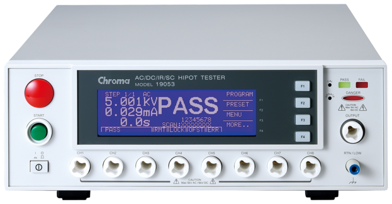
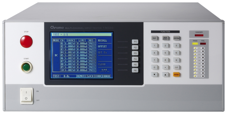
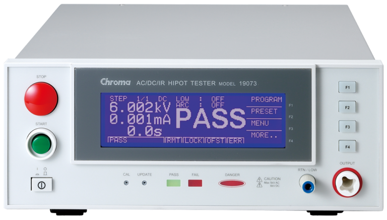
Chroma’s Sentinel Systems are fully customizable automated test solutions designed specifically for medical device electronics, including R&D and production testing, in order to meet global compliance requirements. Sentinel Systems can provide complete Electrical Safety Testing to IEC60601-1 and IEC 60601-2-49 (Multifunctional Patient Monitoring Equipment).
Medical Electronics
IEC60601-1 is mainly intended for product development where safety considerations must be taken into account early in the design phase of a product, however much of it applies to production line testing to ensure manufacturer are shipping safe products. Vital areas of medical device electrical safety testing include hipot test or dielectric breakdown, leakage current, insulation resistance and ground bond testing.
Ensuring The Safety Of Medical Electronics
Vital areas of electrical safety testing for medical products include leakage current, dielectric breakdown, insulation resistance and ground bond testing. To better understand the differences in these tests and others, this article examines the purpose and techniques for each test then offers a detailed discussion on ensuring the safety of medical electronics.
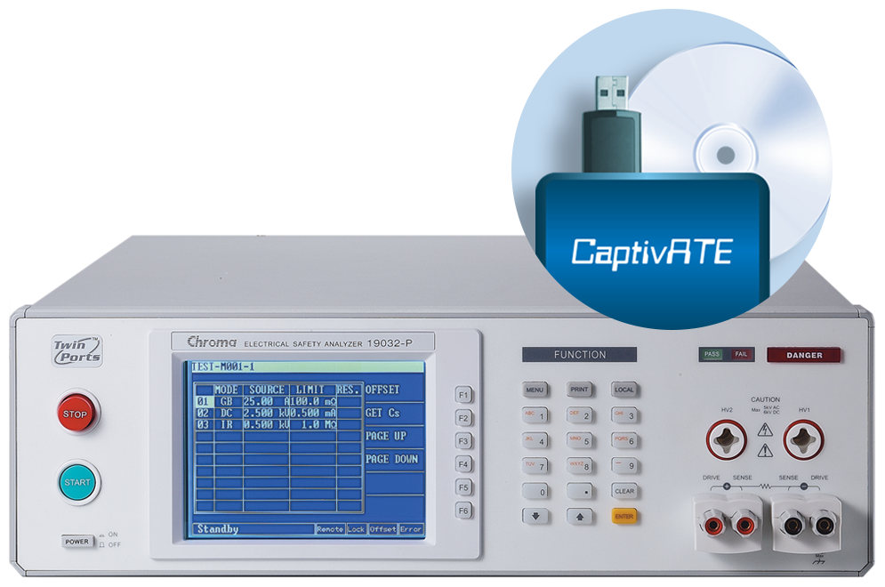
Sentinel I Medical Test System
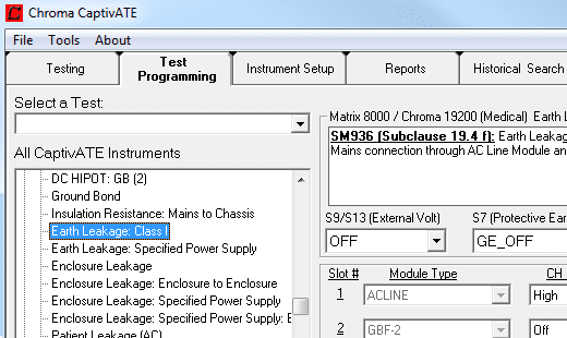
19032 Hipot Analyzer + CaptivATE Automation Software
Automated Medical Device Safety Testing to IEC/EN/UL/CSA 60601-1. The Sentinel I System accommodates Class I, Class II and internally powered medical devices with the following specifications:
- Mains Power up to 4400VA, 0-300Vac
- 1 B-Type Patient Connection
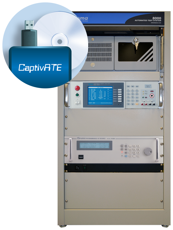
Sentinel II Medical Test System
19032 Hipot Analyzer + CaptivATE + Programmable AC Power
Automated Medical Device Safety Testing to IEC/EN/UL/CSA 60601-1. Sentinel II saves time by scanning patient connections for leakage current without powering down the medical device. The Sentinel II System can be configured to accommodate Class I, Class II, mains and internally powered medical devices with the following configurations:
- Mains Power supply up to 4000VA, 0~300VAC @ 15~1kHZ
- Up to 1 B-Type Patient Connection
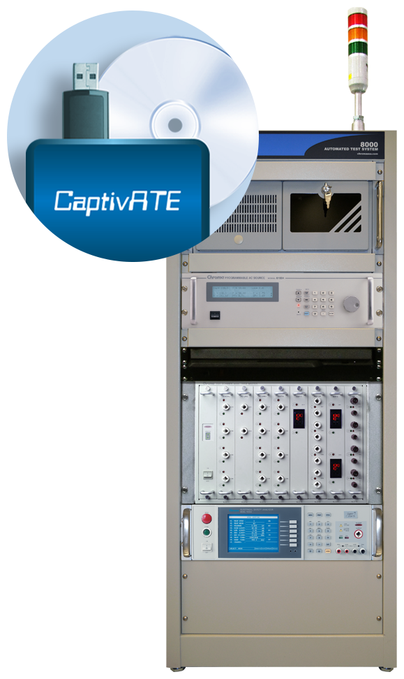
Sentinel III Medical Test System
19032 Hipot Analyzer + CaptivATE + 1500VA or 800VA AC Source + Matrix 8000 Scanning System
Automated Medical Device Safety Testing to IEC/EN/UL/CSA 60601-1 and IEC60601-2-49 (Multifunctional Patient Monitoring Equipment). Sentinel III also scans patient connections for leakage current without powering down the medical device. The Sentinel III System can accommodate Class I, Class II, mains and internally powered medical devices with the following configurations:
- Mains power input up to 4000VA, 0~300Vac @ 15~1kHz
- Up to 16 B, BF, or CF patient connections
- 4 signal inputs/signal outputs
- Other custom configurations available
Sentinel Series: IEC60601 Medical Device Automated Test Systems with IQ/OQ Test Protocol Documents
Sentinel systems are available in 3 efficient configurations with or without an AC power source to fit a wide variety applications from 1 to multiple patient connections. All systems include tests for ground bond, AC and DC Hipot, insulation resistance, and leakage measurements.
CaptivATE Automation Software
CaptivATE provides an off-the-shelf test platform for automating hipot, leakage current, and functional tests. By automating the loading of test setups, sharing test setups plantwide, and combining safety and functional tests into one system, CaptivATE increases efficiency and productivity. For medical devices, software supports IEC60601-1 test requirements, digitally stores product test certificates, and provides IQOQ protocol documentation.
Hipot Testing
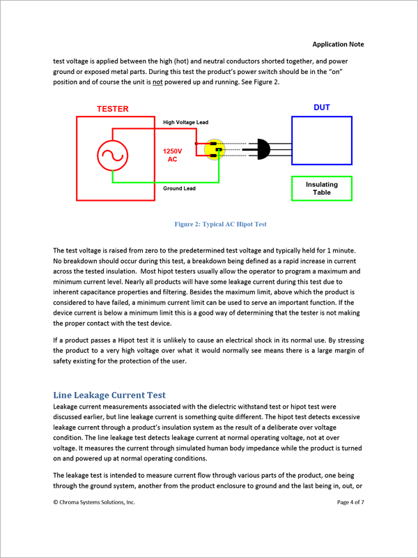
Hipot testing or dielectric strength testing determines the suitability of the dielectric or insulation barrier between hazardous and non-hazardous parts. The IEC60601-1 standard and its supporting standards specify the voltage to be applied to the device under test (DUT) and the acceptance criteria, usually: ‘no breakdown or repeated flashover shall occur’.
Leakage Current Test
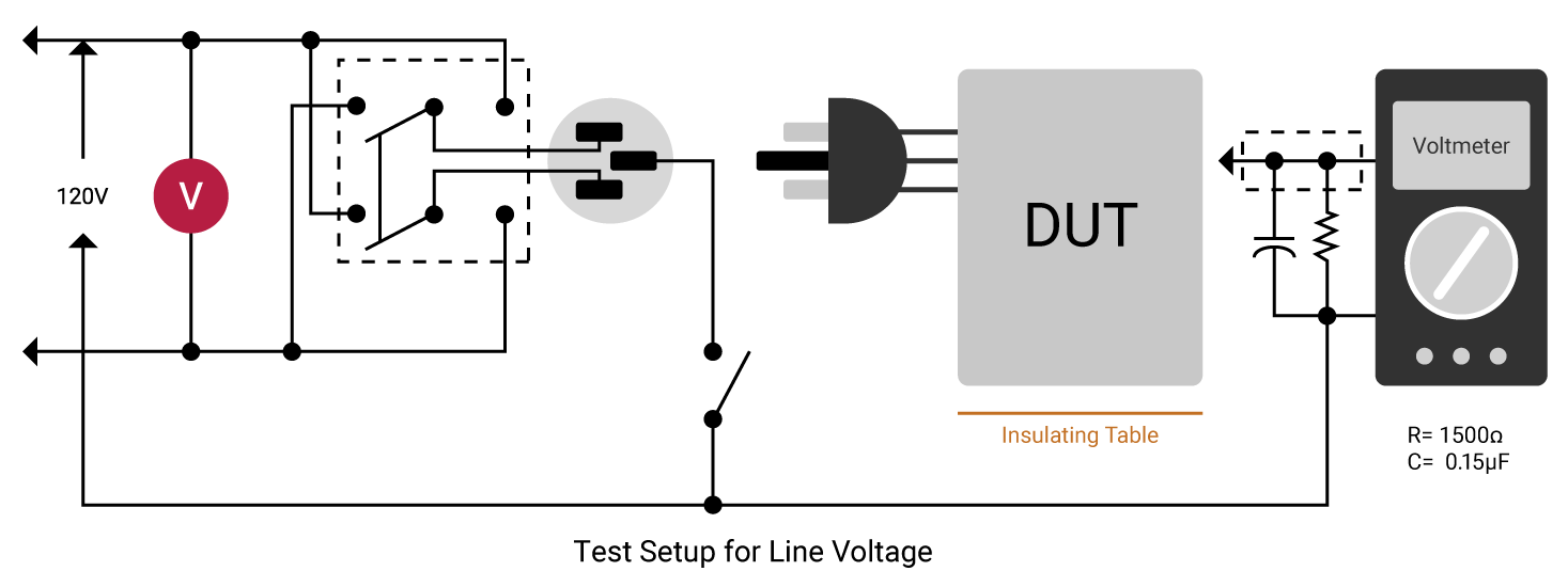
Leakage current is the residual flow of current after HIGH voltage (greater than normal operating voltage) has been applied to the device under test (DUT). This is the current measured in a hipot test. Line leakage current is that measured at 110% of highest rated operating voltage and highest rated frequency. The device under test is turned on and the line leakage is measured across a circuit that simulates the impedance of the human body. There are four types of leakage current: Earth, Touch/Chassis (Enclosure), Patient (Applied Part) and Patient Auxiliary.
4 Types of Leakage Current:
Earth leakage is that line leakage current measured when the ground connector is open, a circuit that simulates the impedance of the human body is inserted and the voltage is measured across it.
Touch/Chassis (Enclosure) leakage is that line leakage current measured by connecting the circuit that simulates the impedance of the human body to any exposed part of the chassis of the DUT. This simulates someone touching the enclosure/chassis of the DUT.
Patient (Applied Part) leakage is that line leakage measured from or between applied parts of the DUT such as the current that might flow from patient leads and sensors on a medical device.
Patient Auxiliary leakage is that line leakage current flowing in the patient in NORMAL use between applied parts of the DUT and not intended to produce a physiological effect.
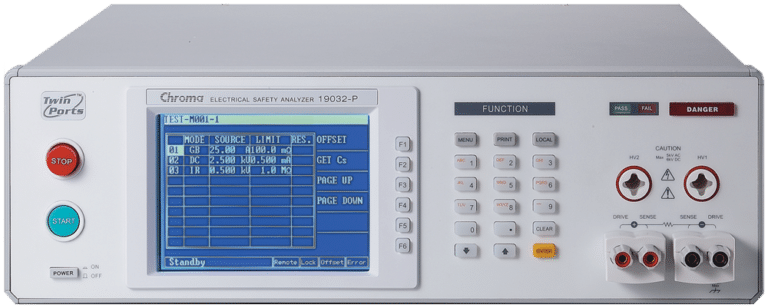
Electrical Safety Analyzer
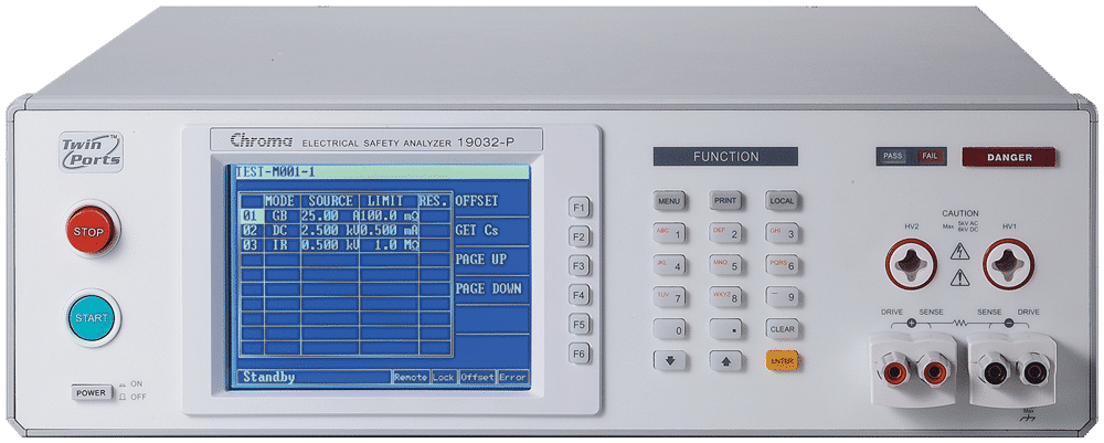
Chroma 19032
Our Electrical Safety Analyzers combine Hipot, Insulation Resistance ( IR), Ground Bond (GB), Leakage Current (LC)/AC LC/DC LC, and Dynamic Function Tests. Savings can be up to 50% of production line space by not having to purchase and rack several safety test instruments. It also increases efficiencies of electrical safety testing and reduces associated labor costs. The 19032 series can test a wide array of of electrical products, including but not limited to: home appliances, medical / Lab / testing equipment, EMI filters, electric vehicles, solar / PV inverters for quality assurance, manufacturing test, and development validation.
Insulation Resistance Test
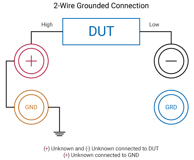
An Insulation Resistance (IR) test measures the total resistance between any two points separated by electrical insulation. The purpose is to determine the strength of the dielectric material (insulation) by stressing it with a high voltage. Voltage (typically 50-1000V DC) is applied to the device under test (DUT) and current is measured. That current flow is made up of three components: dielectric absorption, charging current and leakage current. Dielectric absorption is the physical occurrence of a device absorbing (retaining) charge like an electrolytic capacitor.
Charging current represents itself in the insulation of a device as an instantaneous rise with the applied voltage, and then quickly decays to zero. Leakage current is the component flowing through the insulation after the initial charge of the device. Leakage current is equal to the applied voltage divided by the insulation resistance of the device under test. Remember this residual leakage current from a HIGH voltage test is different than that measured under NORMAL operating conditions.
Ground Bond Testing
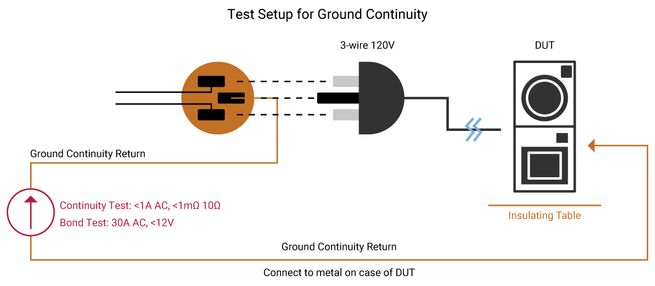
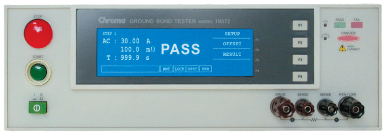
A Ground Continuity (GC) test checks that there is a connection between exposed conductive parts and the ground of the power cord being tested. A low current signal,typically less than 1 Amp is applied to the device under test. A Ground Bond test determines the strength of that ground connection with a high current signal, typically 25Amps. IEC60601-1 specifies that user-accessible conductive parts connected to the safety ground be tested with a current of either 25A or 1.5 times the product’s current consumption, whichever is greater.
The current must source from a maximum no-load voltage of 6V AC. The test is performed for 5 to 10 seconds. The resistance of this ground path equals test current divided by voltage drop. Ohms Law: V=RI, solving for R, R = V/I = 6V/25A = 0.24Ω. IEC60601-1 specifies that the resistance be <0.1Ω on equipment with a detachable power cord and <0.2Ω for equipment with a permanently attached power cord.
